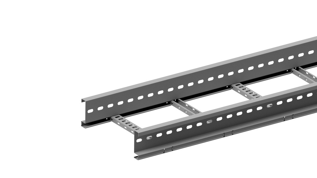
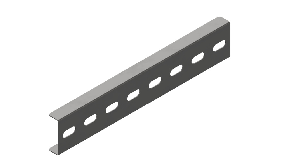
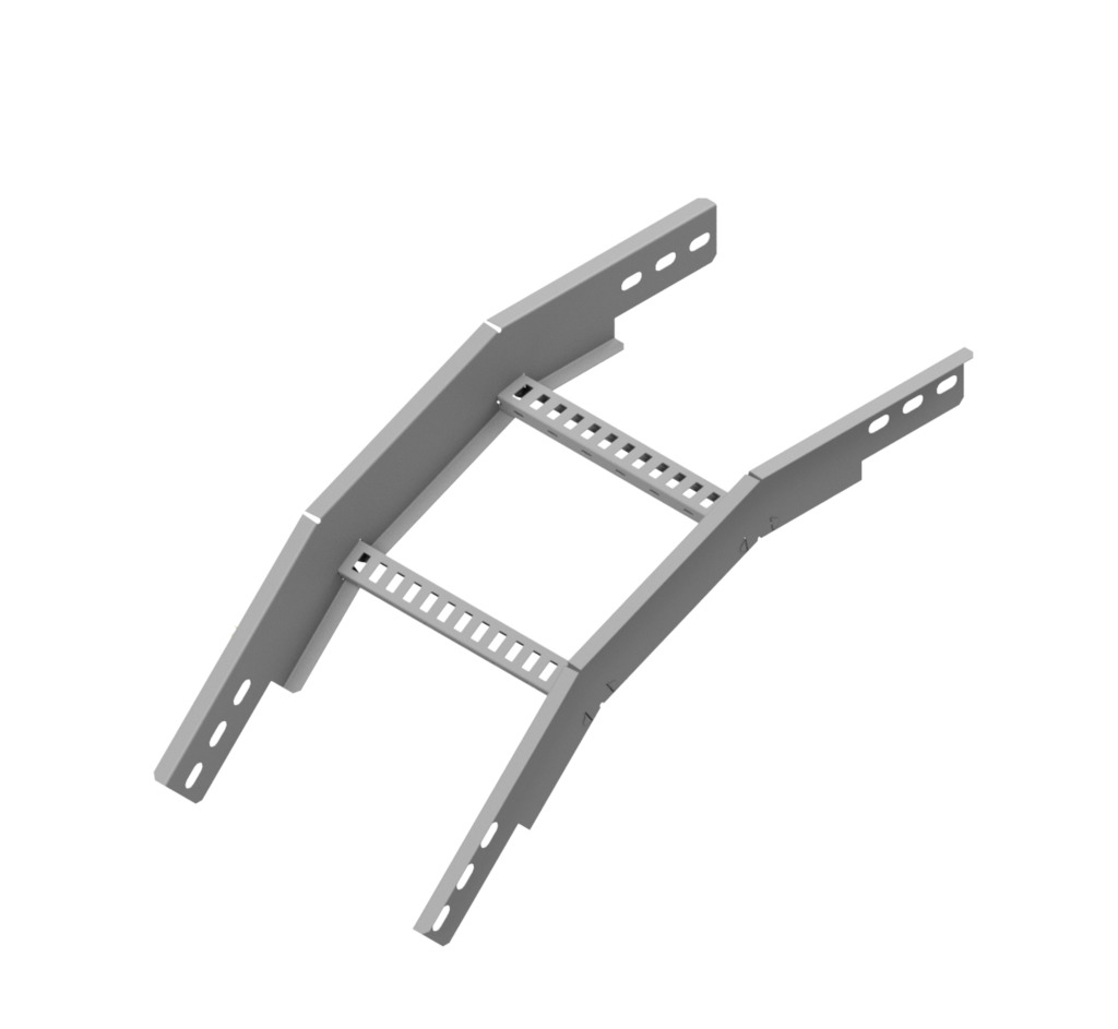
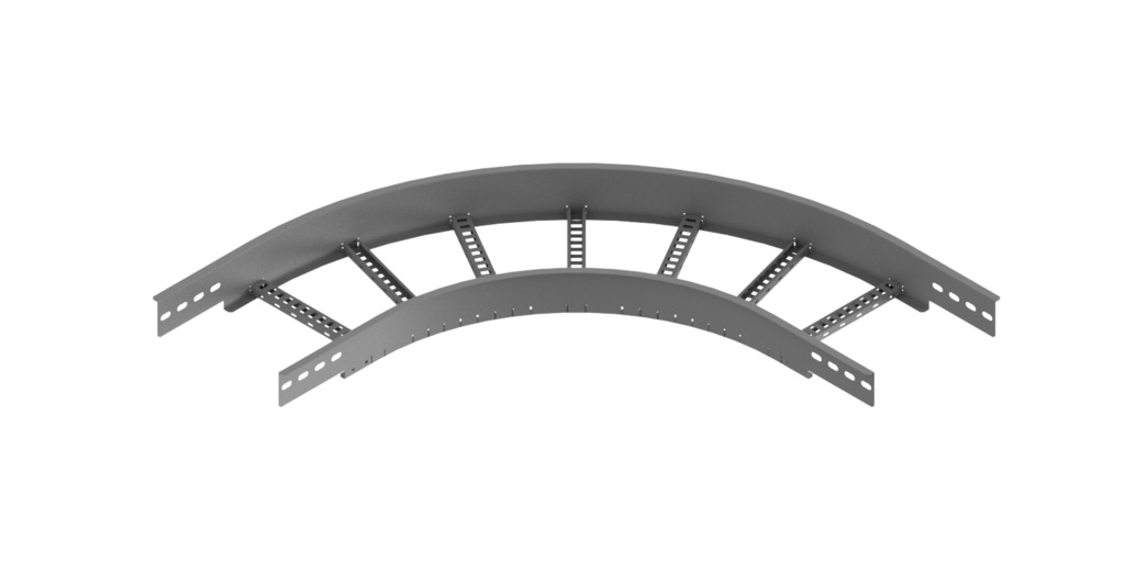
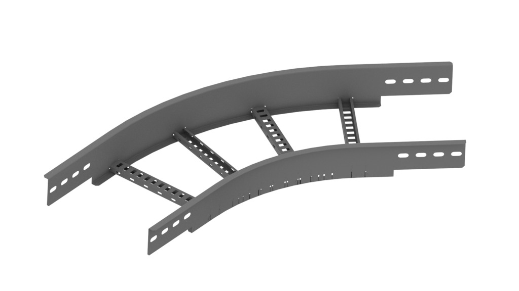
Cable ladder height 125 - KLM125.3
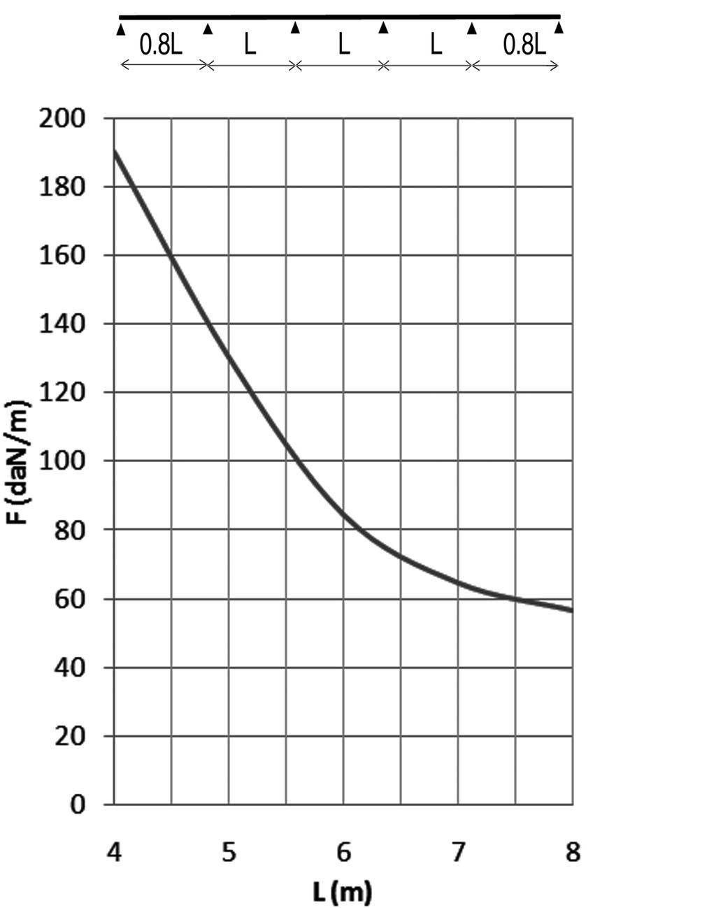
Cable ladder for large support distances up to 8 metres
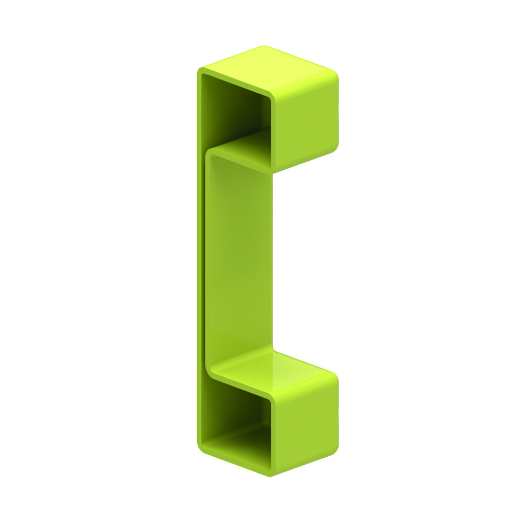
Perforated C datarungs 41x21
Usable inner height: 102 mm
Rung distance: 300 mm
To order: Length 6000 mm
To order: Width 700 - 1200 mm (increments of 100 mm)
ETIM: EC000854
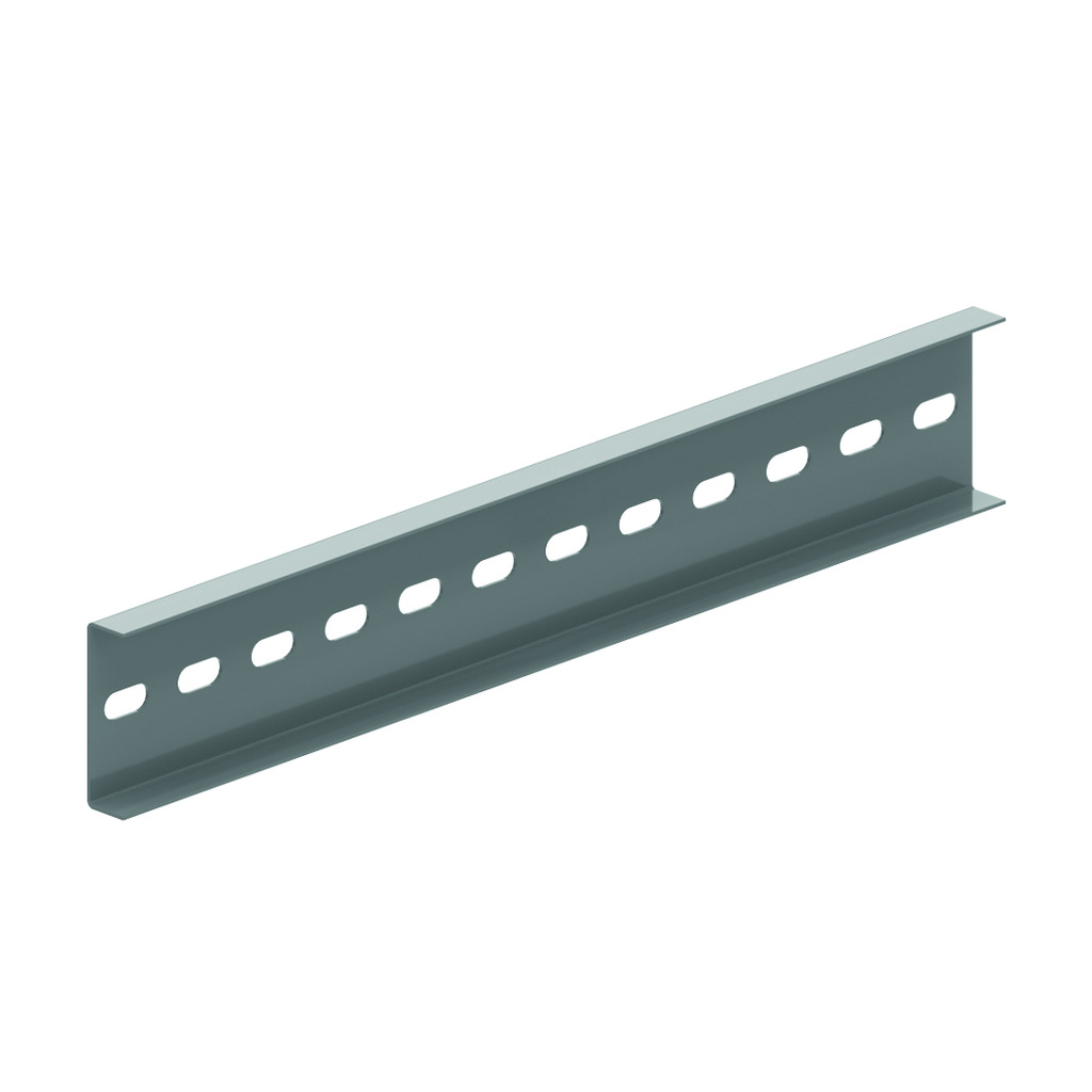
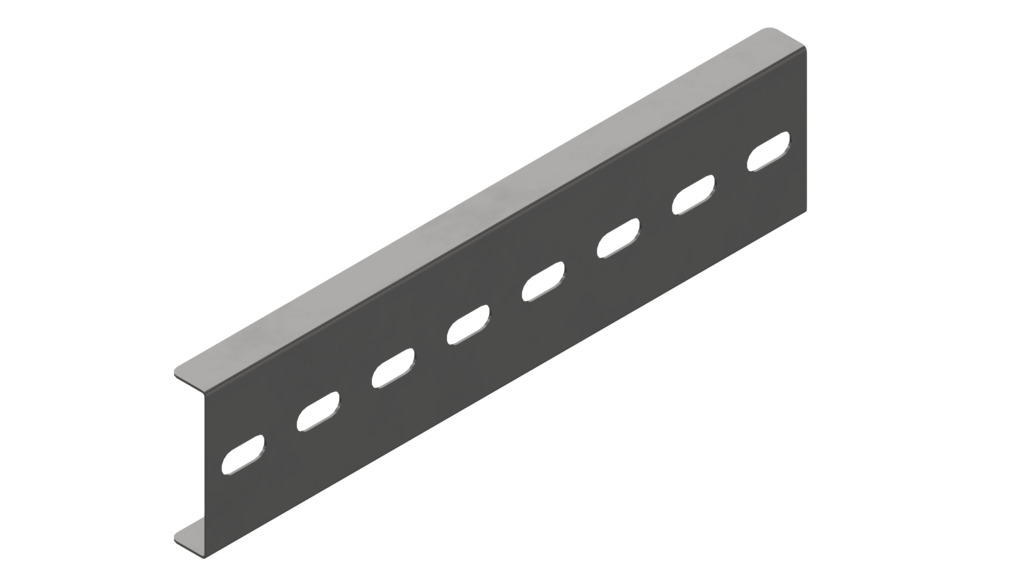
Perforated C datarungs 41x21
Usable inner height: 102 mm
Rung distance: 300 mm
To order: Length 6000 mm
To order: Width 700 - 1200 mm (increments of 100 mm)
ETIM: EC000854
| Reference | Finish |
mm |
mm |
mm |
mm |
kg m |
Stock | Unit | |
| KLM125.150.3 | ZP | 125 | 168 | 1.5 | 3000 | 5.723 | 48 | M | |
| KLM125.200.3 | ZP | 125 | 218 | 1.5 | 3000 | 5.851 | 48 | M | |
| KLM125.300.3 | ZP | 125 | 318 | 1.5 | 3000 | 6.111 | 48 | M | |
| KLM125.400.3 | ZP | 125 | 418 | 1.5 | 3000 | 6.363 | 48 | M | |
| KLM125.450.3 | ZP | 125 | 468 | 1.5 | 3000 | 6.491 | 48 | M | |
| KLM125.500.3 | ZP | 125 | 518 | 1.5 | 3000 | 6.619 | 48 | M | |
| KLM125.600.3 | ZP | 125 | 618 | 1.5 | 3000 | 6.875 | 48 | M | |
| KLM125.750.3 | ZP | 125 | 768 | 1.5 | 3000 | 7.259 | 48 | M | |
| KLM125.800.3 | ZP | 125 | 818 | 1.5 | 3000 | 7.387 | 48 | M | |
| KLM125.900.3 | ZP | 125 | 918 | 1.5 | 3000 | 7.644 | 48 | M | |
| KLM125.1000.3 | ZP | 125 | 1018 | 1.5 | 3000 | 7.900 | 48 | M |