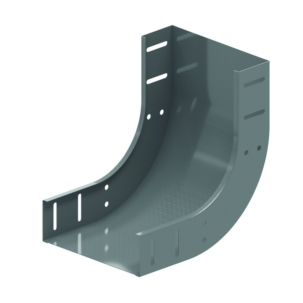
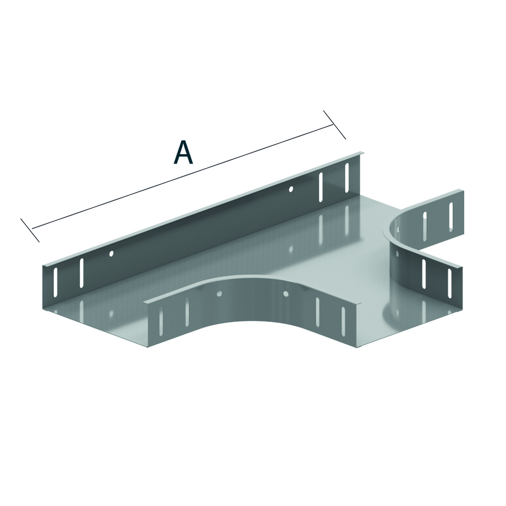
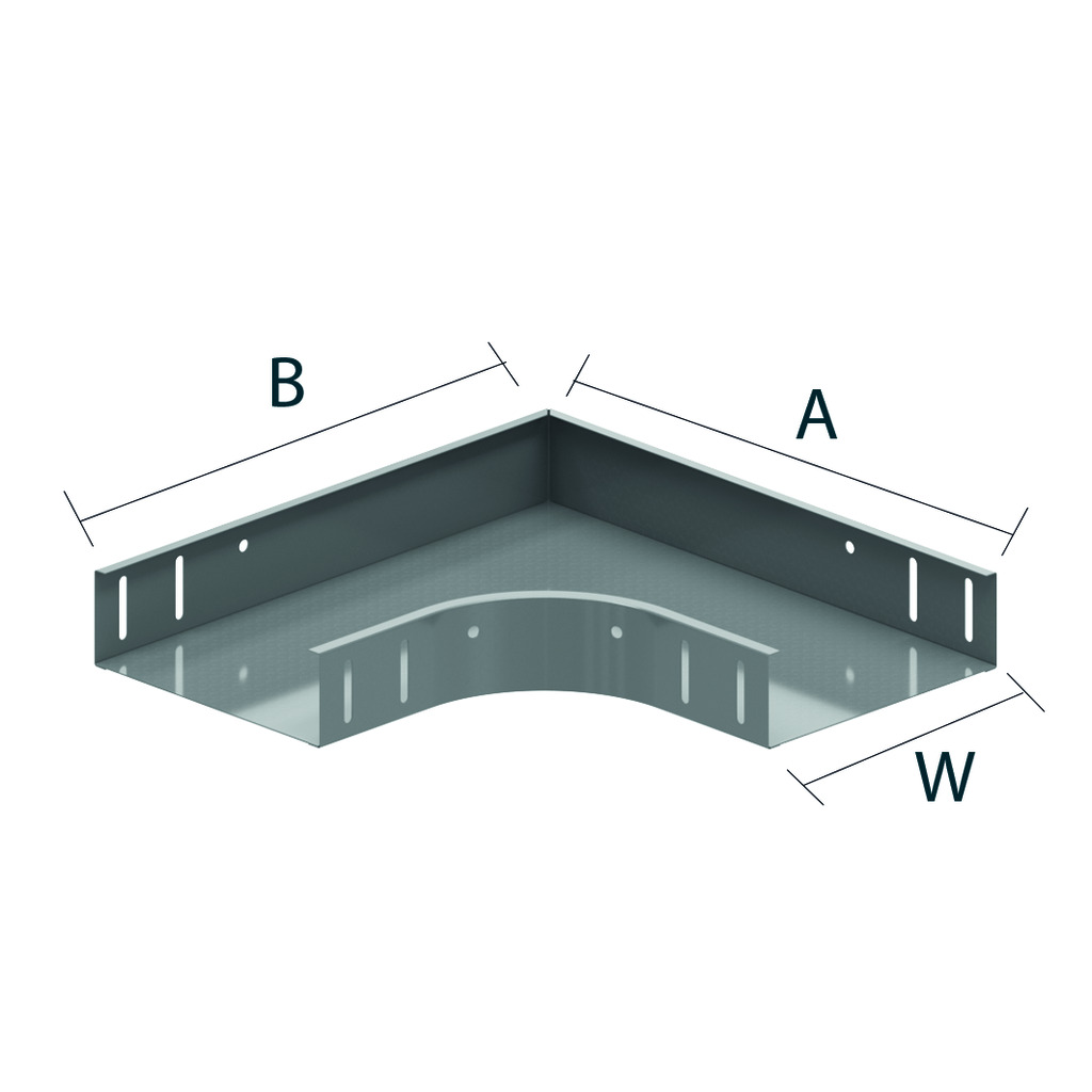
Perforated cable tray - KBS60
Alternative perforation
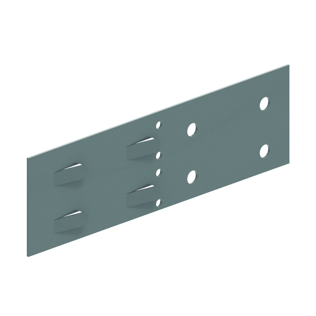
Return flanges
ETIM: EC000047
Return flanges
ETIM: EC000047
| Reference | Finish |
mm |
mm |
mm |
mm |
kg m |
Unit | |
| ZMKBS60.050.075 | DF | 60 | 50 | 0.75 | 3000 | 0.948 | 60 | M |
| ZMKBS60.050.100 | DF | 60 | 50 | 0.90 | 3000 | 1.216 | 60 | M |
| ZMKBS60.100.150 | DF | 60 | 100 | 1.50 | 3000 | 2.549 | 60 | M |
| ZMKBS60.150.150 | DF | 60 | 150 | 1.50 | 3000 | 3.124 | 30 | M |
| ZMKBS60.200.150 | DF | 60 | 200 | 1.50 | 3000 | 3.687 | 30 | M |
| ZMKBS60.300.150 | DF | 60 | 300 | 1.50 | 3000 | 4.780 | 30 | M |
| ZMKBS60.400.150 | DF | 60 | 400 | 1.50 | 3000 | 5.957 | 30 | M |
| ZMKBS60.500.150 | DF | 60 | 500 | 1.50 | 3000 | 7.091 | 30 | M |
| ZMKBS60.600.150 | DF | 60 | 600 | 1.50 | 3000 | 8.243 | 30 | M |
| KBS60.050.075 | - | 60 | 50 | 0.75 | 3000 | 0.948 | 3 | M |
| KBS60.050.100 | - | 60 | 50 | 1 | 3000 | 1.216 | 3 | M |
| KBS60.100.150 | - | 60 | 100 | 1.5 | 3000 | 2.549 | 60 | M |
| KBS60.150.150 | - | 60 | 150 | 1.5 | 3000 | 3.124 | 30 | M |
| KBS60.200.150 | - | 60 | 200 | 1.5 | 3000 | 3.687 | 30 | M |
| KBS60.300.150 | - | 60 | 300 | 1.5 | 3000 | 4.780 | 30 | M |
| KBS60.400.150 | - | 60 | 400 | 1.5 | 3000 | 5.957 | 30 | M |
| KBS60.500.150 | - | 60 | 500 | 1.5 | 3000 | 7.091 | 30 | M |
| KBS60.600.150 | - | 60 | 600 | 1.5 | 3000 | 8.243 | 30 | M |